Do you happen to have a spare factory laying around? I assume not.
Sadly, we also don’t have a spare factory at Critical Manufacturing, which poses some issues for us: how do we ensure that our MES1 will work as expected at the factory, before actually deploying our MES in said factory? This is not a problem solved by standard functional testing - functional tests do help by validating that features work as expected in a vacuum, but what will happen when the factory is producing at full capacity, putting the MES under maximum stress?
This is an especially pertinent problem in the electronics industry: a very nasty mix of high production volumes combined with onerous traceability and quality tracking requirements will bring your MES to its knees if you are not careful! It is therefore critical for projects in this industry to understand how their MES customizations behave under very high loads, because that’s the harsh reality in which these manufacturing execution systems will operate day in and day out.
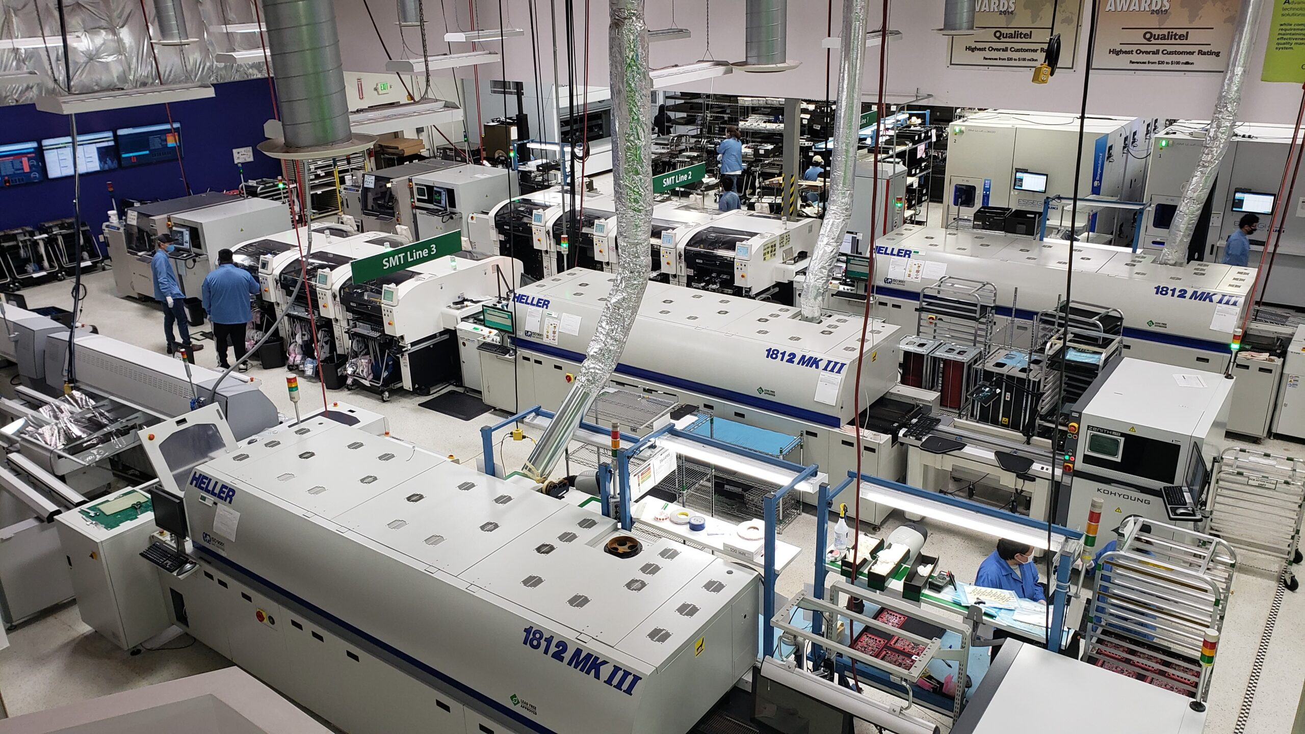
(image source: Qualitel)
So, how do you prove to your stakeholders that your MES system will handle the expected production rate of a factory, without actually running the MES in production? The solution is simple: test the performance of your MES system against a simulated factory.
Only one problem though… how do you simulate a factory?
Introducing the Production Load Generator Link to heading
The Production Load Generator project (more informally known as “PLG”) is a tool that stress-tests an MES system by simulating the factory that the MES system is being built for, hence the name: it’s a Load Generator that replicates the Production Load of a factory in the Critical Manufacturing MES.
The goal of the Production Load Generator is simple: make it as easy as possible for MES customization teams to simulate their customers’ factories, so that performance issues that previously would only show up in production now appear far earlier in the project’s lifecycle. The easier the PLG is to use, the more likely teams are to adopt this tool, so a lot of care and attention was put into the PLG’s overall developer experience.
The Production Load Generator is equal parts a load generator and a factory simulator, which makes it very useful for other purposes within Critical Manufacturing such as showcasing features of the MES that otherwise can only be assessed properly when the MES is running around the clock in production (for example, our reports and dashboards).
Now that you get the broad strokes of what the Production Load Generator is meant to be, let’s see how it works in practice.
So… how does it work? Link to heading
The first thing you should know about the PLG is that it’s not a load generator application that works out-of-the-box.2 It is instead an async C# project that provides you with the abstractions and infrastructure you need to write your load tests (a la K6 or NBomber). You are responsible for setting up the business logic, and the PLG is responsible for executing your business logic in a way that accurately represents a factory’s production flow.
Getting started Link to heading
In order to help users of the Production Load Generator get started with creating scenarios, we provide a LoadScenarioRunner class that acts as the entry point of the application. This class is responsible for connecting to a specific MES environment and running the specified load scenario against that environment.3
class Program
{
    static async Task Main(string[] args)
    {
        await new LoadScenarioRunner()
            .AddLoadScenarios([
                new FirstLoadScenario() // Add your load scenarios here
            ])
            .SetDefaultConfiguration() // Load the appsettings.json file and the env variables
            .RunAsync();
    }
}
Which load scenario is executed, for how long, and against which MES environment is determined by the appsettings.json file:
{
    "TargetEnvironment": "Local",
    "ScenarioToRun": "First load scenario",
    "ScenarioDuration": "00:01:00",

    "Environments": {
        "Local": {
            "HostAddress": "localhost:80",
            "ClientTenantName": "IndustryTemplates",

            "IsUsingLoadBalancer": false,
            "UseSSL": false,

            "SecurityPortalClientId": "MES",
            "SecurityPortalBaseAddress": "http://localhost/SecurityPortal/",
            "SecurityPortalAccessToken": "[Your PAT]",

            "Culture": "en-US"
        }
    }
}
Creating a load scenario Link to heading
Creating a new load scenario is as easy as creating a new class that implements the PLG’s ILoadScenario interface:
internal class FirstLoadScenario : ILoadScenario
{
    public string ScenarioName => "First load scenario";

    // Sets up the load scenario.
    public async Task SetupAsync(IConfiguration configuration)
    {
        // ...
    }

    // Runs the load scenario.
    public async Task RunAsync(CancellationToken cancellationToken)
    {
        // ...
    }

    // Cleanup called after the load scenario execution.
    public async Task TeardownAsync()
    {
        // ...
    }
}
The methods in this class are pretty self-explanatory: you setup your load generators and the MES in SetupAsync, run the load generators in RunAsync until the cancellationToken is triggered, and finally revert all MES configurations to their original state in TeardownAsync.
Everything that I’ve shown so far is just generic infrastructure for running load tests in a standardized manner and doesn’t differ that much from other publicly available load generators. It is nevertheless a necessary foundation on top of which the PLG’s load generators run on.
These load generator classes are the reason for the PLG’s existence: they are excellent at simulating manufacturing processes, and are what make the Production Load Generator uniquely suited for Critical Manufacturing’s factory simulation needs:
The ProductionLoadGenerator class Link to heading
This eponymous load generator works by treating the materials processed by the factory as independent concurrent state machines whose state represents their manufacturing progress, and are able to transition between states by executing MES services.
Users are able to define a state machine for the material by defining handlers which map a particular state to an action. For example, the following state handler table:
$$\begin{array}{ll} \hline \mathbf{State\ Pattern} & \mathbf{Action} \\ \hline \mathtt{\ast @Queued} & \mathtt{dispatch()} \\ \mathtt{\ast @Dispatched} & \mathtt{track\_in()} \\ \mathtt{\ast @InProcess} & \mathtt{track\_out()} \\ \mathtt{\ast @Processed} & \mathtt{move\_next()} \\ \hline \end{array}$$
Would yield the following state machine:

In practice, the actual code is slightly more verbose, but the core idea remains unchanged:
public async Task RunAsync()
{
    ProductionLoadGenerator loadGenerator = new ProductionLoadGenerator()
        .AddHandler(new Handler
        {
            Name = "Queued Handler",
            StatePattern = "*@Queued",
            Handle = async input =>
            {
                // Find a resource to dispatch our material to
                Resource dispatchResource = await input.Entity.GetResourceForDispatchAsync();

                // Dispatch our material
                await input.Entity.DispatchAsync(dispatchResource);

                // Return the new material state.
                // This string will be used by the PLG to find a new handler for the material.
                return input.Entity.State();
            },
        })
        .AddHandler(new Handler
        {
            Name = "Dispatched Handler",
            StatePattern = "*@Dispatched",
            Handle = async input =>
            {
                await input.Entity.TrackInAsync();
                return input.Entity.State();
            },
        })
        .AddHandler(new Handler
        {
            Name = "InProcess Handler",
            StatePattern = "*@InProcess",
            Handle = async input =>
            {
                await input.Entity.TrackOutAsync();
                return input.Entity.State();
            },
        })
        .AddHandler(new Handler
        {
            Name = "Processed Handler",
            StatePattern = "*@Processed",
            Handle = async input =>
            {
                await input.Entity.ComplexMoveNextAsync();
                return input.Entity.State();
            },
        });
}
It’s understandably difficult to get an intuition for how this load generator works just from reading this short synopsis, so if you’re looking for more details about this state machine-based load generator concept, I suggest reading this blog post I wrote back in 2025.
The LineLoadGenerator class Link to heading
While the state machine-based ProductionLoadGenerator is an incredibly versatile simulator, it struggles with modelling queue-based manufacturing processes, such as SMT Lines and car assembly lines. The LineLoadGenerator is a load generator designed for exactly this purpose: simulating manufacturing lines.

(image source: The Seattle Times)
The LineLoadGenerator has two core abstractions: the LineEquipment class which represents a singular machine with inputs and outputs, and the LineLoadGenerator which is responsible for piecing and wiring these LineEquipment objects together into a cohesive production line.
The goal of this load generator is to make the creation of simulated assembly lines as simple as putting lego blocks together, while giving the user full control of the behaviour of these individual blocks.
LineEquipment Link to heading
The LineEquipment class is the core building block of the LineLoadGenerator: it represents a singular piece of equipment in a manufacturing line (i.e. a conveyor belt, a P&P machine, an SMT oven, etc). It has three core properties: the name, the number of inputs and the number of outputs. The outputs of one LineEquipment object are the inputs of another LineEquipment object.4
The LineEquipment class is an abstract class, meaning that you are expected to create subclasses that inherit from LineEquipment and implement the RunAsync method. This method governs the behaviour of the line equipment you are trying to emulate and is expected to run for the duration of the load test.
Here is an example of what a LineEquipment subclass looks like in practice:
/// <summary>
/// Represents a generic MES resource that receives a panel from the input,
/// tracks the panel in and out in the MES, and sends the panel to the next line equipment.
/// </summary>
class MESResource : LineEquipment
{
    public MESResource(string name) : base(name) {}

    protected override async Task RunAsync(CancellationToken cancellationToken)
    {
        Resource resource = await GetObjectByNameAsync<Resource>(Name);

        while (true)
        {
            Material panel = await ReceiveAsync(cancellationToken);

            await resource.LoadAsync();
            await panel.ComplexTrackInAsync(resource);

            await resource.LoadAsync();
            await panel.ComplexTrackOutMaterialAsync();

            await SendAsync(panel, cancellationToken);
        }
    }
}
Pay close attention to the ReceiveAsync and SendAsync methods in the example above: this is how the simulated machine interacts with the outside world - by receiving panels from its inputs, and, once “processing” is done, sending the panels via its outputs.5 6
And what about IoT? Link to heading
You might be wondering: and what about IoT? And what if I also want to stress-test the ConnectIoT layer as part of my load tests? Can I get my LineEquipment objects to communicate via IoT protocols?
Yes, you can! By leveraging the IoT protocol simulator plugins of our IoTTestOrchestrator framework (detailed at length in this blog post by my colleague & IoT expert João Roque), you can get your LineEquipment to talk via whatever IoT protocol you wish.
Here’s an example of a simulated machine that communicates via the Hermes Protocol:
protected override async Task RunAsync(CancellationToken cancellationToken)
{
    while (!cancellationToken.IsCancellationRequested)
    {
        Material panel = await ReceiveAsync(cancellationToken);

        // Send BoardArrived Hermes message
        HermesPlugin!.SendMessage(new BoardArrived
        {
            MachineId = Name,
            UpstreamLaneId = 1,
            SlotId = 1,
            BoardTransfer = BoardArrivalTransferType.Transferred,
            BoardId = panel.Name,
            FailedBoard = FailedBoardType.UnknownQuality,
            FlippedBoard = FlippedBoardType.TopSideUp,
            BoardIdCreatedBy = "UpstreamMachine1",
        });

        // Simulate cycle time
        await LoadGenerator!.Delay(CycleTime, cancellationToken);

        // Send BoardDeparted Hermes message
        HermesPlugin!.SendMessage(new BoardDeparted
        {
            MachineId = Name,
            DownstreamLaneId = 1,
            MagazineId = "magazineId" + DateTime.Now.ToString("HHmmssffff"),
            BoardTransfer = BoardDepartureTransferType.Removed,
            BoardId = panel.Name,
            BoardIdCreatedBy = "UpstreamMachine1",
        });

        await SendAsync(panel, cancellationToken);

        // Simulate the equipment getting ready for receiving the next panel
        await LoadGenerator!.Delay(InterCycleTime, cancellationToken);
    }
}
The IoTTestOrchestrator framework is doing all of the heavy lifting here - connecting to the ConnectIoT driver instance, sending CheckAlive messages, acting as a courier through which we can send and receive IoT messages, etc. It really is an excellent bit of technology that you can take full advantage of in your PLG load tests.
LineLoadGenerator Link to heading
The LineLoadGenerator class is where the LineEquipment building blocks are linked together into simulated manufacturing lines.
The following LineLoadGenerator code:
LineLoadGenerator SMTLine = new LineLoadGenerator()
    .SetName("SMT Line")
    .AddEquipment(new MESResource("PRT01"))
    .AddEquipment(new MESResource("SPI01"))
    .AddEquipment(new MESResource("PnP01"))
    .AddEquipment(new MESResource("PnP02"))
    .AddEquipment(new MESResource("PnP03"))
    .AddEquipment(new MESResource("OVN01"))
    .AddEquipment(new MESResource("AOI01"));
Would result in the following simulated manufacturing line:

Notice how all the LineEquipment are already linked for you - by default, the newly added simulated equipment is automatically connected to the end of the line. Sometimes you can have nice things!
This is just the tip of the iceberg of what the LineLoadGenerator can do: this load generator is more than capable of simulating machines with multiple inputs and outputs and can handle incredibly complex multi-lane assembly lines without issue. You might think this is overkill but I can assure you it’s not: we have seen some truly unique SMT setups over the years at Critical Manufacturing, and the PLG needs this flexibility to be able to simulate them all with ease.
Early results look promising Link to heading
The Production Load Generator has already been used by some teams to validate some performance-critical scenarios, and so far the feedback I’ve gotten by my colleagues is that it’s pretty intuitive to use, which is a massive relief! One of the goals of the PLG is to make load tests against our MES dramatically easier to perform - mission accomplished.
In terms of performance, the PLG has proven to be so effective at stress-testing the MES that teams are becoming limited by our internal development infrastructure - to the point that requests for dedicated database hardware are now being made to open the door for more extensive load tests. This request for more hardware is completely understandable, though… if you want to simulate a factory with 40 SMT lines running concurrently, there’s no going around it: you’re gonna need a bigger boat.

And last but not least, we need to discuss how teams are collecting performance data from their load tests. While the PLG is capable of logging every HTTP request it makes (via the HttpClient’s ActivitySource), teams prefer to lean on our MES’s excellent observability dashboards. One key advantage of leaning on the MES itself for monitoring its performance, is that the techniques used to analyse the performance of the MES during the load test are directly transferrable to analysing the performance of the MES in production.
Final thoughts Link to heading
It’s very rare to be given the opportunity to start a completely new project from scratch, and I couldn’t be happier with how the Production Load Generator is flourishing. To get this far, it took a lot of effort from a lot of people, to whom I’m eternally grateful:
- I’d like to thank Óscar Martins for the political sponsorship and Miguel Torres for the technical sponsorship & guidance.
- I’d like to thank Fábio Reis for promoting this tool to other parts of the company.
- I’d like to thank the entire Electronics Template team for their contributions to the PLG. In no particular order, thank you to Eduardo Oliveira, Flávio Rodrigues, Erik Barba, Roberto García, Oscar Trejo, Isaac Mateus, Daniel Pereira, and Pedro Limas.
- I would like to thank Nuno Nunes for his stewardship of the
IoTTestOrchestratorproject. - I would like to thank Diogo Paredes, Eliana Vieira and Gonçalo Dias for taking a chance on this project, with a special thank you to Francisco Azevedo for his extensive feedback which undoubtedly made the PLG better.
And finally, I would like to thank you for reading my blog post!
-
A Manufacturing Execution System is a software system responsible for the bookkeeping of a factory’s production. It is generally used in highly sophisticated industries, such as the semiconductor industry and the medical devices industry, where a high level of material tracking and control is required. ↩︎
-
But you can absolutely develop a load generator application backed by the PLG if you want! ↩︎
-
Providing this component also comes with another advantage: standardization across projects of how load scenarios are defined, configured, and run. ↩︎
-
This linking of inputs to outputs is transparent to the
LineEquipmentand is entirely managed by theLineLoadGenerator. ↩︎ -
It may help to think of the
LineLoadGeneratoras an implementation of the actor model, with theLineEquipmentobjects being actors that can only communicate with a limited set of other actors by sending or receiving materials. ↩︎ -
And in case you’re wondering, a
SendAsynccall only returns when matched by aReceiveAsynccall from the downstream machine. This handover mechanism is backed by a zero-capacity MPMC queue which is detailed in a previous blog post. ↩︎